Modeling & Simulation
Finite Element Method is widely used in several engineering disciplines because of the tremendours increase in computer power.
Finite Element Method (FEM) is widely used in several engineering disciplines because of the tremendous increase in computer power and commercially available FEM tools. Nowadays, large scale simulations with several millions of degrees of freedom (DOF) are possible. Modeling not only reduces the cost and time in design cycles, but also plays a vital role in understanding the fundamental behavior of the system, especially in the microelectronics industry, where the spatial dimensions are in the range of micrometers to nanometers.
The main goal is to reproduce all occurring electrical and thermo-mechanical phenomena arising during the manufacturing processes of integrated power semiconductors as well as during field application as efficiently as possible. Hence, 3D simulations are performed in addition to 2D design studies.
Research Goals
- Electro-thermal modeling of power electronic systems to evaluate thermal performance of new technological designs (FEM based, as well as electro-thermal modeling on circuit-level using SPICE based techniques)
- Thermo-mechanical modeling of manufacturing process steps, multi-scale and multi-physical modeling of chip-package-PCB interactions
- Material model fitting for an elastic-plastic, time and temperature dependent behavior of materials used in simulations
- Residual stress modeling to investigate the reliability of ICs for new and emerging technologies in order to evaluate new designs, processes, materials and structures
- Delamination and crack propagation studies in power metallization stacks subjected to thermal fatigue

Thermal and Electro-thermal Modeling of Electron Devices
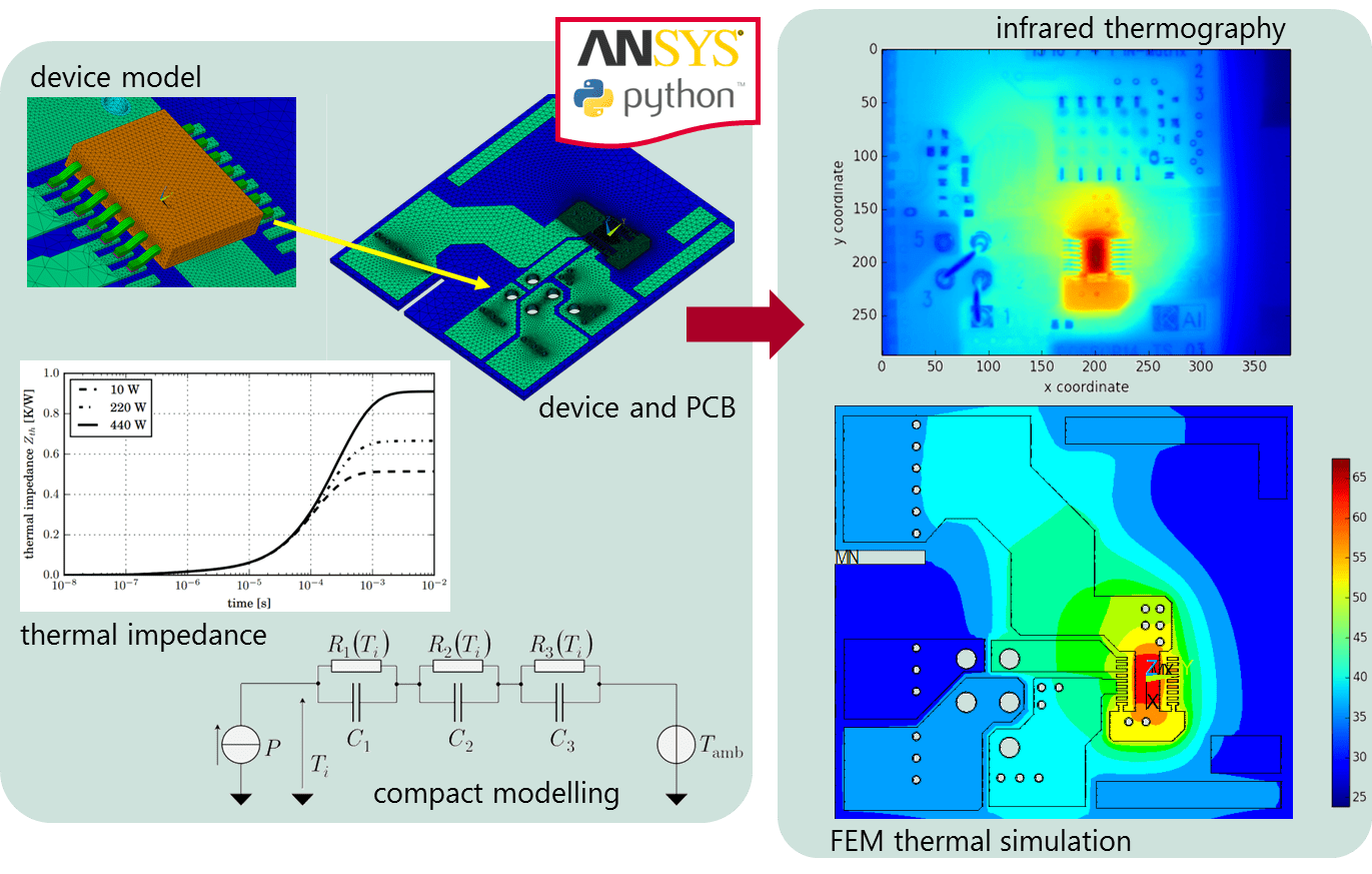
Accurate thermal and electro-thermal modeling of electron devices is mandatory when dealing with reliability of products and to understand how technology, product design and packaging interact together once the product is placed in an application. Furthermore, a correct thermal description is the starting point to reliably assess thermo-mechanical robustness of the considered devices.
To cover all these aspects, a strong interaction between Finite Element Method (FEM) and compact electro-thermal modeling at circuit level (SPICE) is required. A full interaction between FEM simulators, scripting languages (Python), and electrical simulators is an in-house established know-how which renders numerical simulation a tool able to support technology development, product design, packaging and applications.
Moreover, simulations are supported by experiments, where the validity and the accuracy of the developed models can be assessed and eventually improved to precisely describe the given physical problem.
Thermo-mechanical Modeling
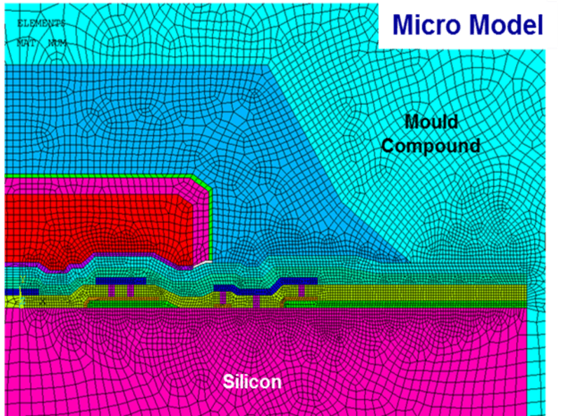
Thermo-mechanical reliability of microelectronics devices is one of major concerns in the industry. Thermally induced stresses & strains in addition to mechanical loadings onto the IC layer stacks during the manufacturing process may lead to reliability problems. However, not only the manufacturing process embraces risks, but also fatigue damage during field application can also endanger the targeted lifetime of the product. In order to asses possible risks and also to guarantee a knowledge based chip design, thermo-mechanical finite element simulations, ideally coupled with electro-thermal simulations, play a vital role.
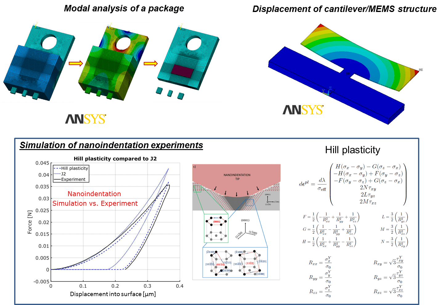
Such simulations entail many challenges such as non-linear behavior of material and geometry and also large size differences from a nanometer-scale of an IC layer to a millimeter-scale package. Therefore advanced modeling techniques are required, such as multi-scale modeling, advanced material constitutive models including time- and temperature-dependent response of the constitutes, contact algorithms, element birth and death and also advanced mechanics theory, such as fracture mechanics to predict interface delamination and fatigue damage. Advanced material constitutive models are based on J2 (isotropic) plasticity as well as in the anisotropic case on Hill plasticity to treat plasticity in brittle materials with strong non-isotropy,
Our applications are mainly multi-layer IC stacks as well as – to a minor extend – cantilever structures, such as MEMS (Microelectromechanical systems).
Parameter Identification for Thermo-mechanical Material Models
The metals used in electronic manufacturing are of vital importance, playing an important role under both electrical and thermal aspects. Unfortunately, they are subject to strong induced thermo-mechanical cyclic stress during the device operative life. Therefore, such metal layers might suffer from cyclic thermo-mechanically induced fatigue.
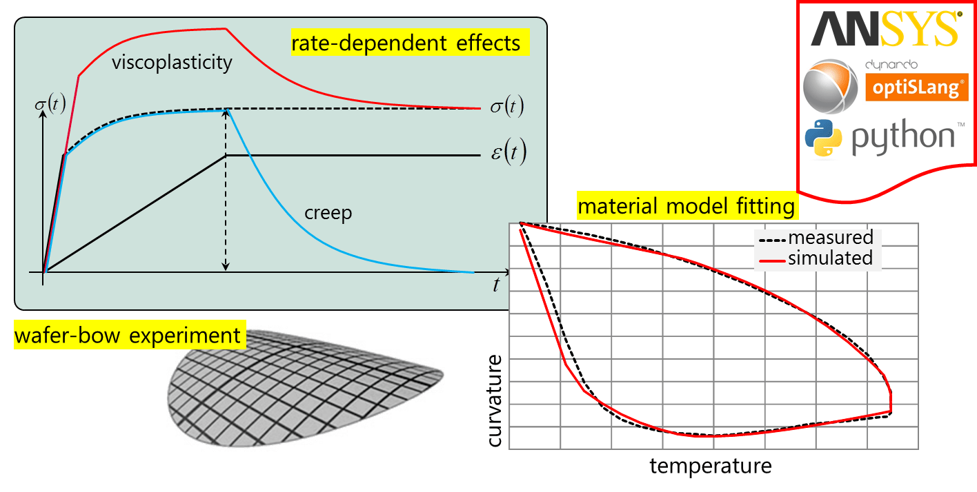
The behaviour of such metals under the typical application conditions is extremely complicated. In general, temperature- and rate-dependent non-linear models are used to account for phenomena like hardening and creep. Many models are available in literature. It is necessary to find the correct set of unknown parameters which provide a physically sound description of the thermo-mechanical response of the considered material.
The sought of such unknowns can rely only on a powerful combination of experiments and simulations, whose response have to match when a physically correct set of parameters is found. To find such set of parameters, state-of-the-art optimization software is used, coupled with advanced thermo-mechanical FEM models and advanced post-processing in an automated manner.
Simulation of Fatigue Damage
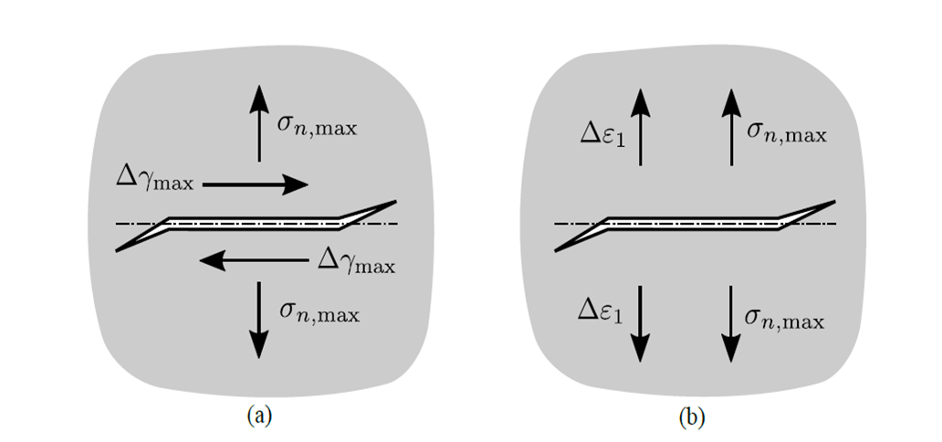
In general, cyclic loading of materials by thermo-mechanical stresses or strains may lead to fatigue damage inside of the material, such as crack propagation and/or interface delamination. Following this, cumulative damage will define the lifetime of the exposed component. In order to understand and study this failure mode in detail, finite element simulations constitute a valuable tool. The used approach to assess cyclic fatigue damage is to apply local continuum damage mechanics to formulate the thermo-mechanical-fatigue conditions, focused on micrometer-sized structures. A multiaxial fatigue criterion, where the orientation of the critical plane is identified by the maximum damage method, describes the onset of micro cracks. These methods combined with the commercially available FEM software ANSYS™ allows the simulation of the whole damage process.
Due to cyclic overload conditions with high temperatures and temperature gradients resulting from high current and high power density pulses, interface delamination may occur at every interface over the whole multi-layer IC stack. Traction separation laws describe the complex damage process of delamination growth. In order to model the possible risk of delamination & decohesion, Cohesive Zone Models (CZM), integrated the framework of finite element methods, are utilized.
Modeling & Simulation Environment
Follow this link to read more about our our Modeling & Simulation Environment.
